I first learned about reflection algorithms when I was working on a feature in our project, where the designers requested a reflective plane.
PART 1: Introduction to Reflection Algorithm
Three implementations can be found in the industry:
- Planar Reflection Camera
- SSR(Screen Space Reflection)
- SSPR(Screen Space Planar Reflection)
We chose to use SSPR at last as the other two were performance-intensive. Still, a brief introduction of them(and their problems) will be made here. You can skip this part if you already know about these algorithms, we are just trying to explain “Why we didn’t choose them”.
Reflection Camera is the most simple and realistic way of a planar reflection implementation. You will create an additional camera, and keep it on a track that is symmetric with your rendering camera by the reflective plane. Then, you use the render texture of that camera to overlay on your plane – that’s it.
The problem is, this camera will usually double your draw-calls. The more complex your scene is, the more it costs. Therefore, it’s only acceptable in simple scenes. We implemented it and used it somewhere else, e.g. character showroom where there are not a lot of objects.
Screen Space Reflection is an algorithm used in most of AAA games for reflective surfaces. It uses the Ray-Marching approach, which is a discounted path-tracing in screen space.
As we know, in the regular rasterization pipeline, we project objects in several spaces in a sequence, namely Model -> World -> Clip -> NDC space.
SSR uses clip space coordinates for UV values and two additional textures for screen normals and depths. The algorithm will then shoot off a ray to each of the pixels requesting a reflective value – the trick is here after the reflection direction is calculated, this ray will move forward for a certain amount of steps. If an intersection is detected by using the depth and normal information on the screen, the pixel’s color will be sampled on the reflective surface.
This algorithm found no problem being utilized on Consoles or PCs, which usually have large enough GPU memories for 2 additional textures. However, it’s not so practical for mobile devices. The depth/normal texture is baked beforehand, which is pressuring for mobile GPUs, Ray-Marching is also too heavy for Mobile GPUs to handle. If we are forced to use low step counts and low-resolution textures, the result could be disappointing.

Some mobile games like Genshin Impact utilize this algorithm due to using a Deferred Pipeline, in such a pipeline, a depth/normal texture is ready to be used, so SSR will be more practical than the cases of a Forward Pipeline.
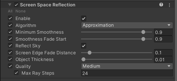
Our project uses Forward Rendering, therefore, we opted to implement SSPR, which is a lighter version of SSR, or “Passive SSR”.
PART 2: How to Do a Passive SSR
SSR is named “Screen Space” due to its nature of using the information in the clip space like depth and screen-normal to calculate intersections.
Remi Genin from Ubisoft developed a new way to simplify this process with a few compromises. His approach can be summarized in one sentence – Replace rays with a simple symmetrical operation.
Since the shader knows about the depth of each pixel, this process is much simpler than SSR. It can be summarized in 4 steps.
- Prepare pixels to accept reflections.
- “Un-project” other pixels on the screen to world space
- Symmetrical operation, project world space points back to screen again
- Render reprojected pixels on reflective pixels
Additional Note: No code will be shown here, as my project is still classified at this point. You can opt to see Remi’s code with this article at the side.
A. Prepare reflective pixels – This is easy, you need a mask on the screen of pixels that require a reflective input, just like SSR. One color channel of your render texture(RT) needs to be written for this purpose. Generally, you make the shader of the reflective plane to do this, and that object needs to be a plane.
B. Un-Project – The main difference between SSR and SSPR is the second/third step. Both algorithms involve an un-projection process, but the usage of that result is a little bit different. Un-project is the process of using the inverse of the Projection/View matrix to get the world-space coordinate of a screen point.
In SSR, each pixel on the screen is un-projected to world space and abstracted as a “pixel object”. This object will have a “thickness” defined, it is virtually a sphere of the pixel’s color, with a radius of the pre-defined thickness value. Screen rays intersected with this sphere will be assigned a corresponding color.
For SSPR, the un-projection process is still used. However, the following step will be different.
C. Symmetrical Operation – After Un-Projection, you get a world position of every pixel. It’s symmetric position about the reflective plane(whose height is passed into shader as uniform) is the position of the reflection.
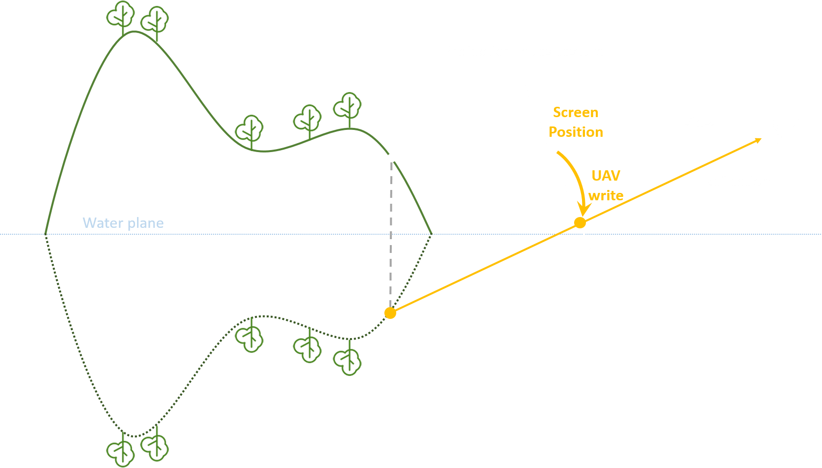
What we need to do next is just as expected: Project this pixel back to the screen space. This way, we have completed a pixel’s screen space planer reflection.
D. Overlay – In step C, if the re-projection hit a pixel on the reflective plane’s mask, the color of this reprojection is ought to be the reflected color. Therefore, overlaying this result on your plane will give the correct render.
PART 3: Problem of Passive Reflection Calculation
Remi mentioned a depth problem where two source pixels might be reflected on the same reflective pixel – Then they cause depth conflict, resulting in flickering pixels. This problem is trivial to solve by bringing in depth comparation.
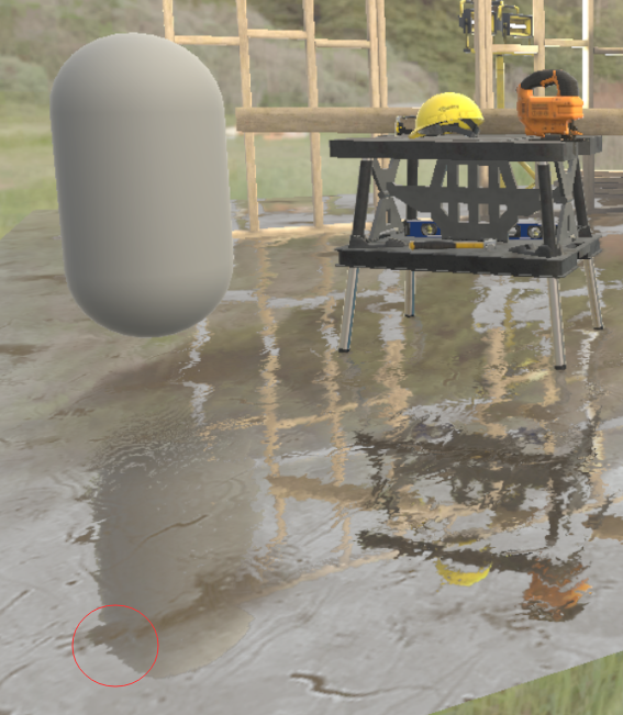
The real problem we encountered is “Reflection Holes”.
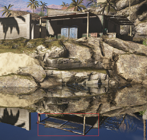
In Remi’s demonstration, we can see these gaps embarrassingly sticking out on the reflected plane. The cause of such gaps is the intrinsic weakness of the “passive” approach.
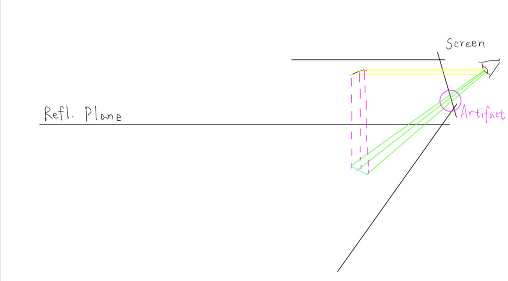
In this sketch, the reflected object (roof) shares a very small area on the screen, but it has a very sharp gradient of depth. However, its reflection can occupy a much bigger area on the screen. In such cases, gaps appear due to the lack of source pixels.
This is the weakness aforementioned. In a passive approach, the reflection of the object has no more pixels than its source object. Once the source object is placed close to parallel to the reflective plane, ugly artifacts appear when the camera is looking down.
We struggled with this problem for a while and find two potential solutions.
Temporal Reprojection
This is the solution used by Remi Genin in Ghost Recon. The mindset of it is similar to TAA. The game will save the reflection result of the previous frame and give it a random amount of jittering, then combine it with the current frame.
This makes gaps much less obvious, but some remains of the previous frame might appear on the water plane if players shake the camera rapidly.
Post-processing UV Filling
This solution is inspired by Colin Leung’s Filling methods. In his filling-hole pass, he sweeps the whole result texture by 2×2 cells to see if a pixel in such cell has a drastically different alpha value compared to others.
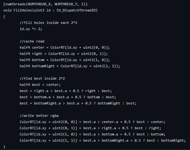
If such a pixel is found, it will be filled with the value of the best pixel inside the cell. This methods works but it creates some artifacts, namely spikes on reflections.
We came up with a better idea called UV Filling.
A. We changed our algorithm to write the source pixel’s UV coordinates in two different channel, like this:
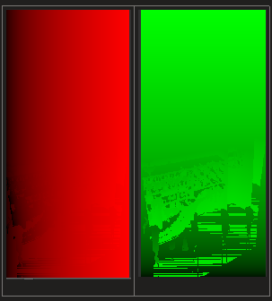
B. When calculating reflections, instead of sampling the color texture directly, we sample the UV from this index texture, then use it to sample the camera color.
C. What we can do now is run Colin’s hole detection on V values only. We will only fill the pixel that has a drastically different v value with its surrounding pixels and only if this pixel is on the reflective plane.
Note: What is a “drastically different” v value? Normally, two adjacent pixels’ v value difference is at most 1/TexSize. In our case, a difference larger than that can only happen when one of the pixel’s UV is altered by reflection.
This avoids the problem of causing horizontal spikes and fills the small cracks just like Colin’s algorithm. It will still cause some vertical spikes but they are naturally unnoticeable.


Combining this with Temporal Reprojection can almost completely solve the gap problem. Some extreme cases might appear unfillable, though.